
In this article, we discuss the tasks of an assembler, linker and loader. We also discuss the design issues faced by both assemblers and linkers.
Table of contents.
- Introduction.
- The workings of an assembler.
- Design issues: Assembler.
- Design issues: Linker.
- Summary.
- References.
Introduction.
An assembler is responsible for converting source code into target code and therefore just like the compiler, an assembler will have stages such as lexical analysis, management of the symbol table and back-patching.
It is important to note that the output from an assembler is still further away from an executable program ready to be run on a computer.
The workings of an assembler.
We shall start from a program that is ready to be executed and work our way backwards so as to understand how an assembler performs its tasks.
A running program.
A running program consists of four components namely code segment, stack segment, data segment and registers.
Code and data segments relate to each other through addresses of locations in the segments which are stored in the machine instructions and in the prefilled part of the data segment.
An operating system will set registers of the hardware memory manager unit such that the address spaces of the code and data segments start at zero for each running program, regardless of the segments' location in memory. This is an issue as we shall come to see in the following sections.
The executable.
To run a program's contents, this file is loaded into memory using a loader which is an integrated part of the operating system thereby making it invisible.
All initialized parts of the program derive from the executable code file whereby all addresses are based on segments starting at zero.
The loader reads these segments and creates a stack segment then jumps to a predetermined location in the code segment to start the program.
Apart from the code segment and data segment, the executable code file can also contain other data such as the initial stack size, execution start address etc.
Linking.
Each object file will carry its own code and data segments contents, the task of the linker is to combine these into the code and data segments of an executable file.
It does this by making copies of the segments, concatenating them, then writing them to the file.
A problem exists concerning addresses inside the code and data segments. Code and data in the object files relate to each other through addresses but since the object files were created without knowledge of how they will be linked. Remember the address space for each code or data segment for each object file starts at zero.
To solve this means that addresses inside the copies of all object files need to be moved to their actual positions during linkage.
An example
Assuming that the length of a code segment in the first object file a.o is 1000 bytes, then the second code segment from another object file b.o will start at the location with machine address 1000.
For this the linker must have relocation information - information about positions in the object segments containing addresses and address information i.e whether the address refers to the code or data segment.
Relocation information can be in the form of bitmaps where bits correspond to each position in the object code and data segments at which an address may be located or in the form of a linked list.
Another problem involves code and data segments in object files containing addresses of locations in other program object files or in library object files.
This is solved by external symbols or external names which mark a location L in an object file whose address can be used in other object files.
The location L is referred to as an external entry point. Object files refer to L using an external reference.
Object files contain information about external symbols they reference and the external symbols they provide entry points to. All this information is the stored in an external symbol table.
For example given an object file a.o containing a call to printf routine at location 500, this file will have explicit information in the external symbol table that it references the external symbol printf at location 500.
If the library object file printf.o has the body of printf starting at location 100, the file will have explicit information in the external symbol table that is features the external entry point at address 100.
The linker is responsible for combining these two pieces of information and update the address at location 500 in the copy of the code segment of the file a.o to the address of location 100 in the copy of printf.o once the position of this copy with respect to other copies has been established.
Linking of three code segments
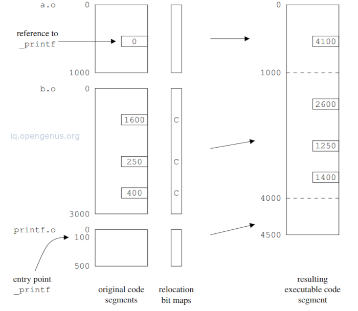
From the above, the segments derive from the object files a.o, b.o and printf.o. The length of the code segment b.o is assumed to be 3000 bytes and for printf.o to be 500 bytes.
b.o contains three internal addresses referring to locations 1600, 250 and 400.
a.o contains an external address of the external symbol printf
printf.o contains one external entry point - the location of printf.
Although not included here, code segments for a.o and printf.o will contain many internal addresses.
Relocation bit maps are efficient compared to linked list since segments will contain a high percentage of internal addresses.
In the linking process, concatenation of the segments is followed by updating of the internal addresses in the copies of a.o, b,o, printf.o by adding the positions of those segments to them.
Positions are found by scanning the relocation maps which will also indicate if the address refers to the code segment or data segment.
Finally it stores the external address of printf which computes to (1000+3000+100) = 4100 at location 100.
We also see that an object file will have the four components, that is, the code and data segments, the relocation bit map and the external symbol table.
Design issues: Assembler.
The main problem in construction of an assembler is the handling of addresses both internal - referring to locations in the same segment and external - referring to locations is segments of other object files.
handling internal addresses.
References to locations in the same code segment or data segment take the form of identifiers in assembly code.
An example
.data
    ...
    .align 8
var1:
    .long 666
    ...
.code
    ...
    addl var1,%eax
    ...
    jmp label1
    ...
label1:
    ...
    ..
The fragment starts with material for .data data segment which contains a 4-byte location .long aligned on an 8-byte boundary filled with 666 and labeled with var1 identifier.
Following this we have the material for .code code segment containing a 4-byte addition from the location var1 to register %eax, a jump to label label1 and the its definition(label1) among other instructions.
The assembler reads the code and assembles the bytes for the segments in two different arrays.
When the above fragment is read the .data directive is first encountered and it directs it to start assembling into the data array.
Source material for data segment is translated to binary and results are stored in the data array.
The .code directive is now met and the assembler switches to assembling into the code array and while translating this segment, it meets the instruction addl var1, %eax for which it assembles the proper binary pattern and register indication including the value of the data segment label var1, 400.
The results are stored in the array in which the code segment is being assembled.
The assembler marks the location as 'relocatable to the data segment' in the relocation bit map.
When jmp label1 instruction is encountered, the assembler cannot perform a similar action since the value of label1 is not known.
Back-patching can solve this problem, that is the assembler keeps a backpatch list for each label whose value is not known.
For example, the backpatch list for label L will contain all addresses ,... of the locations in the code and data segments being assembled, into which the value of L must be stored, and therefore when an applied occurrence of the label L is encountered and the assembler decides that it's value must be assembled into location A, address Ai is inserted in the backpatch list for L and the location Ai is zeroed.
The resulting arrangement is as follows.
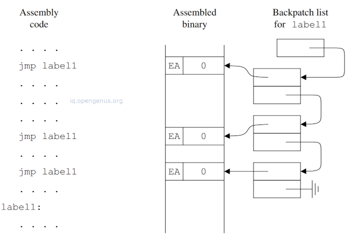
The image above shows the assembly code, the assembled binary code and a backpatch list for the label label1.
When the defining occurrence of L is found, the address of the position it labels is determined and assigned to L as its value.
The backpatch list is processed and for each entry value of L is stored in .
Two-scans assembly can also be a solution whereby the assembler will process an input file twice. The first scan determines the values of the labels. The assembler then goes through the described conversion process without assembling the code.
In the second scan the values of all labels are known therefore translation will take place.
Handling external addresses.
An example of external symbols and addresses of an object file summarized in its external symbol table,
| External Symbol | Type | Address |
|---|---|---|
| options | entry_point | 50 data |
| main | entry_point | 100 code |
| printf | reference | 500 code |
| atoi | reference | 600 code |
| printf | reference | 650 code |
| exit | reference | 700 code |
| msg_list | entry_point | 300 data |
| Out_Of-Memory | entry_point | 800 code |
| fprintf | reference | 900 code |
| exit | reference | 950 code |
| file_list | reference | 4 data |
The above table specifies that the data segment has an entry point named options at location 50, the code segment's entry point named main at location 100, the segment refers to an external entry point printf at location 500.
There is also a reference to an external entry point named file_list at location 4.
Looking at the numbers in the address column, for entry points, the number represents a value of the entry point, for references, it represents the address where the value of the referred entry point must be stored.
This table is easily constructed during translation then the assembler produces a binary version and places it in its proper position in the object file with the code and data segments, relocation bit maps and other header and trailing material.
The linker can also create tables for debugging of the translated program by using the information from the compiler which can be enough to allow a debugger to find exact variables and statements originating from a code fragment.
Design issues: Linker
A linker reads object files and appends each of the four components to the appropriate one of the four lists.
It also retains information about lengths and positions of components.
Relocation is straightforward to relocate internal addresses and link external addresses.
It then writes code and data segments to the executable code file, it also has the option to append the external symbol table and debugging information.
By this stage translation is done, however, real world linkers are much complex than this.
First the situation around object modules is much more complicated in that, many object file formats have features for repeated initialized data, special arithmetic operations in relocatable addresses, conditional external symbol resolution and much more.
Secondly, linkers have to go through large libraries to find the required external entry points. Advanced symbol table techniques speed up this process.
Thirdly, linker writers are under pressure to produce fast linkers however, a source of inefficiency is found in processing external symbol tables, in that, for each entry point, the entire table is scanned to find entries with the same symbol which can then be processes.
This process take O() time complexity where n represents the number of entries in the combined external symbol table.
This is solved by sorting thereby bringing entries with the same symbols together.
Summary.
Assemblers translate symbolic instructions generated for a source code module into a relocatable binary object file.
A linker combines some relocatable binary files, probably library object files into an executable binary program file.
A loader loads the executable binary program file into memory for execution.
The code and data segments of a relocatable object file consist of binary code derived from symbolic instructions.
Relocatable binary object files contain code and data segments, relocation information and external linkage information.
References.
- Modern Compiler Design 2nd Edition Dick Grune, Kees van Reeuwijk
- Introduction to Compilers and Language Design 2nd Edition Prof. Douglas Thain