
Get this book -> Problems on Array: For Interviews and Competitive Programming
Reading time: 20 minutes
In this article, we demonstrate the key components of Verilog Programming for FPGA (Field Programmable Gate Array). With the knowledge, you can build basic circuits in Verilog and will be the first steps in mastering hardware stimulation using Verilog.
There are three basic ideas in Verilog:
- Breaking circuits into various building blocks called modules
- Define a module
- Connect various modules
Communication between modules
Communication between modules is done through ports. Ports are of three types:
- Input
- Output
- InOut
How a problem is defined?
Example of 4029 counter:
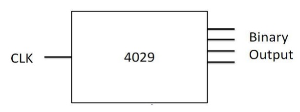
4029 Counter is defined by:
- Name: 4029
- Input Ports: One
- Output Ports: Four
- Size
- Driver type
- Internal Logic: At every rising edge of the clock, increment the output by one
Module
A module is a Black Box in Verilog with inputs, outputs and internal logic working.
A module is defined as
module <specific type>(<port list>);Defining ports
There are two ways to define ports:
Way 1:
input clk;
 input reset;
 input enable;
 output a,b,c,d;
Way 2:
input clk;
 input reset;
 input enable;
 output [3:0] out;
Drivers
We need drivers for a module in order to interact with the ports and describe its logical working.
There are two types of drivers:
- REG: Can store a value (for example, flip-flop)
- WIRE: Cannot store a value, but connects two points (for example, a wire)
When are Ports defined as wires?
We do not need to stores the values of these ports in our logical block.
Example:
- clk
- reset
- enable
When are Ports defined as Registers?
We need to store them so that we could modify their values when required.
Example: out
Defining Internal Logic
All the arithmetic as well as logical operators in Verilog are similar to C, except ++ and -- which are not available in Verilog.
Conditional statements are also similar to C with following modifications:
- { is replaced by begin
- } is replaced by end
Combinational circuits are acyclic interconnections of gates. Output is a function of current input only.
Output depends on current input and current state.
always block
always @(condition)
begin
  // code
end
-
Blocks starting with keyword always run simultaneously.
-
@ symbol is used to specify the condition which should be satisfied for the execution of this block
-
always: The code in this block will keep on executing.
-
always @(a): The code in this block will be executed every time the value of a changes.
-
always @(posedge clk): This block is executed at every positive edge of clk
-
It is an abstraction provided in Verilog to mainly implement sequential circuits
-
It is used for combinational circuits
Blocking and Non-blocking statements
Non-blocking assignments happen in parallel.
Example:
always @ ( #sensitivity list # ) begin
B <= A ;
C <= B ; (A,B) = (1,2) -> (B,C) = (1,2)
end
Blocking assignments happen sequentially.
Example:
always @ ( #sensitivity list # ) begin
B = A ;
C = B ; (A,B) = (1,2) -> (B,C) = (1,1)
end
Points to note:
- Use always@( * ) block with blocking assignments for combinational circuits
- Use always@( posedge CLK) block with nonblocking assignments for sequential circuits.
- Do not mix blocking and non-blocking assignments
Connecting various modules
- Various modules are interconnected to make a larger circuit (or module).
- Each sub-module has a separate Verilog file.
- A sub-module may have another submodule in its circuit.
- One needs to indicate the top level module before synthesis.
Example:
module 4029(input wire clk, output
[3:0]reg out);
Instantiation
- It is used to interconnect various modules
- In the above example, we need to instantiate the two sub-modules in the top level module
- This is done like:
 wire [3:0] c;
 4029 counter (.clk(clk), .out(c) );
 7447 decoder (.in(c), .bcd(bcd));
Congratulations, you have the basic coding knowledge of Verilog
Once mastered the details of this article, your next step should be to browse through some Verilog examples and take a deeper look into design concepts.