
Open-Source Internship opportunity by OpenGenus for programmers. Apply now.
Table of Contents
- Introduction
- 1.1 Historical Background
- Objectives of This Article
- IPv6 Architecture
- 2.1 Address Structure
- 2.2 Header Format
- 2.3 Extension Headers
- Addressing and Routing
- 3.1 Address Allocation
- 3.2 Routing Protocols
- 3.3 Neighbor Discovery Protocol (NDP)
- Transition from IPv4 to IPv6
- 4.1 Dual Stack Approach
- 4.2 Tunneling Mechanisms
- 4.3 Translation Techniques
- Security in IPv6
- 5.1 IPsec
- 5.2 Privacy Extensions
- IPv6 adoption
- Conclusion
1. Introduction
The Internet Protocol (IP) has long been a cornerstone of computer networks and plays a critical role in enabling communication over the Internet. The protocol was originally developed as IPv4, which has been used since the early days of the Internet. However, as the number of networked devices increased, IPv4 faced significant challenges, particularly the exhaustion of available addresses (Lai et al., 2010). This growing demand required the development of a new protocol, which led to the development of IPv6.
IPv6, the latest version of the Internet Protocol, was specifically designed to address the limitations of IPv4, particularly the shortage of IP addresses. It offers a significantly larger address space and is therefore able to support the ever-growing number of devices and services connected to the Internet. Beyond simply expanding the address space, IPv6 introduces several improvements, including hierarchical addressing and routing, improved forwarding efficiency, and better support for mobility (Cui et al., 2012; Gonzalez, 2021; Naagas et al., 2021).
1.1 Historical Background
Internet protocols have undergone significant evolution over several decades, adapting to the growing demands for data transmission, interoperability, and global connectivity across diverse applications.
The origins of these protocols can be traced back to the late 1960s with the development of ARPANET (Advanced Research Projects Agency Network), funded by the U.S. Department of Defense. ARPANET was designed to connect multiple computers within a single network, and it initially relied on the Network Control Protocol (NCP) (Winett & Sammes, 1973) for basic data exchange between hosts.
In 1974, Vint Cerf and Bob Kahn introduced the Transmission Control Protocol (TCP), which was later integrated with the Internet Protocol (IP) to form the TCP/IP suite. This combination became the foundational protocol for ARPANET and significantly improved communication capabilities by incorporating features such as error checking and data segmentation. The introduction of TCP/IP as a standard in 1983 was a pivotal moment and led to its widespread adoption across various networks.
As the Internet expanded in the 1980s and 1990s, the need for standardized protocols to support a wide range of applications became increasingly apparent. In this regard, the Internet Engineering Task Force (IETF) proved to be an important organization responsible for developing and promoting voluntary Internet standards. Through its series of Requests for Comments (RFCs), the IETF facilitated discussions and established standards for various aspects of network protocols.
Introduction of IPv6 as a Solution to IPv4 Limitations
IPv4 was developed in the early 1980s as part of the ARPANET project and laid the foundation for the modern Internet. IPv4 was standardized in 1981 by RFC 791 and uses a 32-bit addressing scheme, allowing approximately 4.3 billion unique addresses (2^32).
An IPv4 address such as “158.80.164.3” consists of four 8-bit addresses. Bit octets that together form the 32-bit address. The subnet mask is used to distinguish between the network and host portions of the address. For example, in the address “192.168.0.2” with the subnet mask “255.255.255.0,” “192.168.0” identifies the network, while “2” identifies the specific host within that network.
Initially, this addressing scheme was sufficient because the number of devices connected to the Internet was relatively small. However, as technology evolved and the number of devices connected to the network - from PCs to mobile devices - rapidly increased, the limitations of IPv4 became clear.
The major challenges associated with IPv4 include:
- Address exhaustion: By the late 1990s, it was clear that the pool of available IPv4 addresses would soon no longer be sufficient to serve the growing number of devices connecting to the Internet.
- Security Concerns: IPv4 was not designed to have inherent security features, leading to vulnerabilities that can be exploited by malicious actors.
- Network Address Translation (NAT): To reduce address exhaustion, NAT has been widely adopted, allowing multiple devices on a local network to share a single public IP address. While this extended the lifespan of IPv4, it introduced additional complexity and potential end-to-end connectivity issues.
- On February, 2011, ICANN announced the release of the last block of IPv4 addresses, signaling a critical shortage that was making it increasingly difficult for new or expanding companies to obtain IP addresses.
Development of IPv6 as a Response to IPv4 Challenges
In response to the challenges posed by IPv4, including address exhaustion and security vulnerabilities, the Internet Engineering Task Force (IETF) began work on a successor protocol IPv6 in the early 1990s. The main goals of IPv6 were to significantly expand address space, improve security features, and simplify routing and network configuration.
Key Features of IPv6:
- Expanded Address Space: IPv6 uses a 128-bit addressing scheme that allows for an astronomical number of unique addresses approximately 340 undecillion (3.4 x 10^38 or 2^128). This massive expansion was critical to supporting the growing number of devices connected to the Internet.
- Built-in Security Features: Unlike IPv4, IPv6 was designed with security as a fundamental component. It includes mandatory support for IPsec (Internet Protocol Security).
- header structure: The header format in IPv6 has been optimized compared to IPv4. The simplified header reduces processing overhead on routers, resulting in improved performance and more efficient routing.
Google reported that between 41% and 66% of its global user base accessed the Internet over IPv6, with fluctuations depending on the day of the week. This indicates growing but regionally varying adoption of IPv6 around the world.
Regional Variations (Google, n.d.) in IPv6 Adoption:
- Asia-Pacific: India has high adoption rates, exceeding 70%.
- North America: The U.S. shows significant adoption around 50%.
- Europe: Germany and France lead with rates above 70%.
- Africa: Adoption is lower, below 20%, due to economic and infrastructure constraints.
Challenges in Adopting IPv6:
- Legacy Systems: Many organizations continue to rely on legacy systems that are not compatible with IPv6. These systems are often deeply integrated into business operations, making the transition difficult.
- Cost Implications: Updating infrastructure to support IPv6 can be expensive, especially for organizations with extensive networks. This cost factor remains a significant barrier to widespread adoption.
- Lack of Awareness: There is still a general lack of understanding about the benefits and necessity of adopting IPv6. This lack of awareness hinders the momentum needed for a broader transition.
Objectives of This Article
The main goal of this article is to provide a comprehensive examination of IPv6, focusing on its architecture and the features that make it a more suitable protocol for the future of the Internet. Specific objectives include, Exploring the architectural design of IPv6. This includes an exploration of the key features and improvements that differentiate IPv6 from its predecessor and make it better suited to meet the evolving needs of global connectivity challenges and strategies, associated with this critical transition. The aim is to make the content informative yet easy to digest and to provide sufficient depth without overwhelming the reader. Due to time frame and scope limitations, this article does not provide a comprehensive comparison between IPv4 and IPv6. However, necessary comparisons are made where necessary to improve understanding. The article also avoids speculation about future trends or predictions about the future of IPv6.
2. IPv6 Architecture
The IPv6 address structure is fundamentally different from its predecessor IPv4's 32-bit addresses. An IPv6 address consists of 128 bits and is represented as eight groups of four hexadecimal digits separated by colons. For example, an IPv6 address might look like this:
2001:0db8:85a3:0000:0000:8a2e:0370:7334
The 128-bit address space theoretically allows a maximum of 2^128 unique addresses. This number is extraordinarily large, representing approximately 340 undecillion (3.4 x 10^38) unique addresses. To put this into perspective, every person on Earth could be assigned trillions of unique IP addresses. This massive address space accommodates not only traditional computing devices, but also the rapidly growing number of Internet-connected devices such as smartphones, tablets, smart devices, and Internet of Things (IoT) devices.
2.1 Address Types
IPv6 defines three primary address types: unicast, multicast and anycast.
1. Unicast
- A unicast address uniquely identifies a single interface on an IPv6-enabled device. When data packets are sent to a unicast address, they are delivered directly to the interface associated with that address. This type of communication is one-to-one communication involving a single sender and a single receiver.
- Types of Unicast Addresses:
- Global Unicast Address: These addresses are routable across the global Internet, similar to public IP addresses in IPv4. They fall into the address range of
2000::/3. - Link-local address: Link-local addresses are used for communication within a local network segment and cannot be routed beyond their local link. These addresses begin with the prefix
FE80::/10. - Unique Local Address (ULA): ULAs are similar to private IP addresses in IPv4 and are used for local communications within an organization. They fall into the address range
FC00::/7.
- Global Unicast Address: These addresses are routable across the global Internet, similar to public IP addresses in IPv4. They fall into the address range of
2. Multicast
- A multicast address identifies a group of interfaces, typically across multiple devices. When packets are sent to a multicast address, they are delivered to all interfaces that belong to that multicast group. This enables efficient one-to-many communication without requiring individual addresses for each recipient.
- The multicast address range starts with
FF00::/8. - A special type of multicast address, called a solicited node multicast address, is automatically generated from the unicast or anycast address of an interface. It is mainly used for neighbor detection and duplicate address detection.
3. Anycast
- Anycast addresses allow packets to be sent to multiple interfaces, but the packets are only delivered to the closest interface based on routing metrics. This means that while multiple devices can share the same anycast address, only the closest one (in terms of network topology) will respond to requests sent to that address.
- Anycast addresses use the same format as global unicast addresses, but must be explicitly configured on devices.
Hexadecimal Notation
IPv6 addresses are represented as 128-bit numbers, usually in hexadecimal format. This representation consists of eight groups of four hexadecimal digits separated by colons (:). Each group represents 16 bits (or two bytes) of the address. An example of a full IPv6 address in this notation is:
2001:0db8:0000:0042:0000:8a2e:0370:7334
To simplify this tedious notation, several conventions have been introduced:
-
Leading zeros: Within any group of four hexadecimal digits, leading zeros can be omitted. For example, 0042 can be written as 42. Using this convention, the previous example can be shortened as follows:
2001:db8:0:42:0:8a2e:370:7334 -
Zero compression: If an address contains consecutive groups of zeros, they can be replaced with a colon (::). However, this compression can only be applied once in an address to avoid ambiguity. For example:
2001:db8::42:0:8a2e:370:7334 -
Mixed Notation: In some cases, an IPv6 address contains an embedded IPv4 address, represented in mixed notation. This happens when the last 32 bits of the IPv6 address represent an IPv4 address. An example is:
::ffff:192.168.1.1
2.2 Header Format
The IPv6 header consists of a fixed-length portion that is 40 bytes long. This fixed size allows routers to process packets more efficiently because they can consistently read the same number of bytes without having to parse variable-length fields. The structure of the IPv6 header is as follows:
- Version (4 bit): This field indicates the version of the Internet protocol used. For IPv6, this value is set to 0110 in binary, which is 6 in decimal.
- Traffic Class (8 bits): This field is used for Quality of Service (QoS) purposes. It allows distinguishing between different types of traffic, enabling prioritization based on application requirements.
- Flow Label (20 bits): This field is used to identify packet sequences that require special handling by routers, e.g. B. Real-time data streams.
- Payload length (16 bits): This field indicates the length of the payload after the header in bytes. This allows routers to determine how much data follows the header.
- Next Header (8 bits): This field identifies the type of header that immediately follows the IPv6 header. It can specify different protocols such as TCP, UDP or ICMPv6.
- Hop Limit (8 bits): Similar to the TTL (Time To Live) field in IPv4, this field indicates how many hops a packet can make before it is dropped by a router. Each router reduces this value by one; If it reaches zero, the packet is dropped.
- Source Address (128 bits): This field contains the IP address of the originating node that sent the packet.
- Destination Address (128 bits): This field holds the IP address of the intended recipient node.
Comparison of IPv4 and IPv6 Header Formats
Header Size:
- IPv4: The header size varies between 20 bytes to 60 bytes, depending on the options used.
- IPv6: The header size is fixed at 40 bytes, regardless of any additional options.
Addressing:
- IPv4: Utilizes 32-bit addresses, which allows for approximately 4.3 billion unique addresses.
- IPv6: Utilizes 128-bit addresses, providing an astronomical number of unique addresses (~3.4 x 10^38).
2.3 Extension Headers
In IPv6, extension headers provide a flexible mechanism for introducing optional functionalities without complicating the main header structure. These headers follow the main IPv6 header and offer extensibility to the protocol, allowing various network services to be implemented efficiently.
Hop-by-Hop Options Header: This header carries optional information that must be examined by every node along the packet’s path. It is primarily used for network-layer options that require processing by all routers between the source and destination.
Routing Header: The Routing Header allows a source node to specify one or more intermediate nodes (waypoints) that a packet should traverse on its way to the final destination. This capability can be used to influence the path that packets take through the network.
Fragment Header: When a packet exceeds the Maximum Transmission Unit (MTU) size on a network link, it needs to be fragmented into smaller packets. The Fragment Header contains information necessary for reassembling the fragments at the destination, ensuring the original packet can be accurately reconstructed.
Destination Options Header: Similar to the Hop-by-Hop Options Header, this header carries optional information, but it is only processed by the destination node. This header allows for the inclusion of options that are relevant only to the endpoint of the communication.
Authentication Header (AH): The Authentication Header provides integrity and authentication for IP packets, ensuring that the packet has not been altered during transit and verifying the identity of the sender. While not an extension header in the traditional sense, AH plays a crucial role in securing IPv6 communications.
Encapsulating Security Payload (ESP): The Encapsulating Security Payload provides confidentiality, in addition to integrity and authentication. ESP encrypts the data being transmitted, And protecting it from unauthorized access during transmission over potentially insecure networks.
Flow of an IPv6 Packet Across the Network
-
Initiating the Request: A user initiates a request from their computer (source) to access a website hosted on a server (destination). This request triggers the creation of an IPv6 packet.
-
Packet Construction: The computer constructs an IPv6 packet, embedding its own IPv6 address as the source and the IPv6 address of the web server as the destination. The packet also includes other necessary headers and data payload.
-
Local Network Transmission: The packet is first sent across the local network, traveling through switches that forward it based on MAC (Media Access Control) addresses. These switches operate at the data link layer, ensuring the packet reaches the local router.
-
Router Processing: Upon reaching a router, the router examines the packet’s destination IPv6 address. It checks its routing table to determine the best path toward the network where the web server is located. The router then forwards the packet to the next hop along this path.
-
Traversal Through Intermediate Routers: If the packet needs to pass through multiple networks to reach its destination, intermediate routers repeat the process. Each router along the path checks its routing table and forwards the packet toward the next router closer to the destination network.
-
Final Router to Destination Network: When the packet reaches the final router connected to the destination network (the web server’s network), this router forwards the packet directly to the destination IPv6 address specified in the packet.
-
Processing by the Web Server: The web server receives the IPv6 packet, reassembles it if necessary, and processes it according to the relevant application-layer protocol, such as HTTP or HTTPS. This process might involve serving a web page or handling data transactions.
3. Addressing and Routing in IPv6
3.1 Address Allocation
Global Unicast Addressing
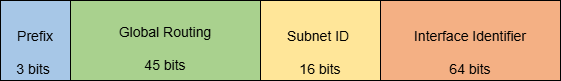
Global Unicast Addresses are unique identifiers for interfaces on devices that are intended to be reachable over the Internet. These addresses are equivalent to public IP addresses in IPv4 and are globally routable. The structure of a global unicast address is divided into three parts:
48-bit Prefix and Global Routing: This part is allocated by the Internet Assigned Numbers Authority (IANA) to regional Internet registries (RIRs), which then distribute these prefixes to local ISPs or organizations.
16-bit Subnet Identifier: This portion is used by organizations to define subnets within their allocated address space.
64-bit Interface Identifier: Typically derived from the device’s MAC address or generated using a process like Stateless Address Autoconfiguration (SLAAC), this part uniquely identifies an interface within the subnet.
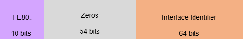
Link-Local Addresses
Link-Local Addresses are used for communication within a single network segment or link. These addresses are not routable beyond their local link.
-
Prefix (FE80::/10): Link-local addresses start with the prefix FE80::/10.
-
54 bits of Zeros: Following the prefix are 54 bits set to zero, ensuring the address is unique within the local link.
-
64-bit Interface Identifier: This is typically derived from the device's MAC address or generated randomly to ensure uniqueness within the link.
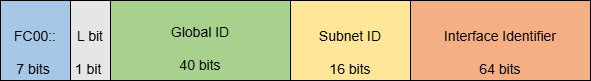
Unique Local Addresses
Unique Local Addresses (ULAs) serve a similar purpose to IPv4 private addresses (e.g., those defined by RFC1918). They are intended for use within internal networks and are not routable on the public Internet.
-
Prefix (FC00::/7): ULAs begin with FC00::/7, with FD00::/8 often used to denote locally assigned addresses.
-
L Bit: The L bit (the 8th bit) determines how the ULA was generated:
- If set to 1 (FD00::/8), it indicates a locally assigned ULA, created independently by the organization.
- A 0 value would indicate a globally assigned ULA.
-
40-bit Global ID: This portion ensures that ULAs are unique across different networks, preventing address conflicts when different networks are interconnected.
-
16-bit Subnet Identifier: This part allows organizations to divide their ULA space into subnets.
-
64-bit Interface Identifier: As with global unicast addresses, this is used to identify individual interfaces within a subnet.
Address Aggregation and Hierarchical Addressing
Address aggregation in IPv6 combines several smaller subnets into a single, larger address block. This technique helps reduce the number of entries in routing tables and makes the forwarding of data packets more efficient.
Hierarchical addressing supports this process by organizing addresses based on logical groupings, such as geographic location or organizational structure. For example, an ISP could receive a large block of addresses and assign smaller portions to its customers while managing all subnets under a single, aggregated route. This approach simplifies network management and keeps the routing infrastructure more scalable and organized.
3.2 Routing Protocols
As networks transition to IPv6, various routing protocols have been adapted or developed specifically for this protocol.
RIPng (Routing Information Protocol next generation)
RIPng is an extension of the original RIP protocol designed specifically for IPv6 networks. It works with a distance vector routing algorithm, meaning that it determines the best path to a destination based on the number of hops (i.e. the number of routers between the source and the destination).
RIPng has a maximum hop count of 15, which limits the size of the network it can manage. It sends routing updates every 30 seconds, and it uses route poisoning to mark failed routes as unreachable to prevent routing loops.
Operation: Each router maintains a route table and regularly shares this information with its neighbors. When a router receives an update from another router, it compares the received routes with its own and updates its table if it finds a better route (i.e. fewer hops).
EIGRP for IPv6 (Enhanced Interior Gateway Routing Protocol)
OSPFv3 is an adaptation of the OSPF protocol for IPv6. It uses a link-state routing algorithm in which routers maintain a complete map of the network topology.
OSPFv3 uses Link-State Advertisements (LSAs) to share information about routers and their links. It supports network areas to organize routing efficiently and converges quickly when the network topology changes.
Operation: Each router sends LSAs to all other routers in its area. These LSAs are used to create a link-state database (LSDB). Using Dijkstra's algorithm, each router calculates the shortest path tree from itself to all other nodes in the network based on the LSDB.
EIGRP for IPv6 (Enhanced Interior Gateway Routing Protocol)
EIGRP for IPv6 is Cisco's proprietary routing protocol that combines features of distance vector and link-state protocols.
EIGRP for IPv6 uses Diffusing Update Algorithm (DUAL) to ensure that routing is loop-free and converges quickly. It calculates routing metrics based on bandwidth, delay, load, reliability, and MTU size.
Operation: Routers send hello packets to discover neighbors and establish neighborhoods. Once neighbors are established, they exchange routing information using update packets. EIGRP maintains a topology table with all learned routes and their metrics.
IS-IS for IPv6 (Intermediate System to Intermediate System)
IS-IS for IPv6 is a link-state protocol that has been adapted from its original use with IP networks to support IPv6.
IS-IS for IPv6 supports both IP and non-IP protocols and operates at Layer 2. It functions similarly to OSPF but has different mechanisms for discovering and communicating with neighbors.
Operation:IS-IS routers send hello packets, called “LSPs” (Link State PDUs), to discover neighbors. Each router builds a complete view of the network topology based on LSPs received from other routers.
MP-BGP4 (Multiprotocol Border Gateway Protocol version 4)
MP-BGP4 extends the capabilities of BGP4 to support multiple address families, including IPv6. It allows BGP to carry routing information for different types of networks.
MP-BGP4 can handle multiple address families like unicast and multicast over different protocols, including IPv4 and IPv6.
Operation: BGP peers exchange route advertisements using UPDATE messages that include path attributes specific to each address family.
3.3 Neighbor Discovery Protocol (NDP)
The Neighbor Discovery Protocol (NDP) is a fundamental component of IPv6 and is intended to replace the Address Resolution Protocol (ARP) used in IPv4. NDP operates at the link layer and is essential for various network functions, including discovering neighbors, determining link layer addresses, and managing reachability information.
NDP includes several key components:
- Neighbor Solicitation (NS): This message is sent by a device to request the link-layer address of a neighbor or to verify its reachability. When a device needs to communicate with another device on the same local network but lacks the link-layer address, it sends an NS message as a multicast request.
- Neighbor Advertisement (NA): Upon receiving an NS message, the target device responds with a Neighbor Advertisement. This message contains its link-layer address and can also indicate whether it is reachable. The NA can be sent as a unicast or multicast response.
- Router Solicitation (RS): Devices use Router Solicitation messages to request router advertisements from local routers when they join a network. This helps them learn about available routers and their configurations.
- Router Advertisement (RA): Routers send Router Advertisements periodically or in response to RS messages. These advertisements contain important information such as network prefixes, default gateway addresses, and other configuration parameters.
- Redirect: Redirect messages are used by routers to inform hosts of better next-hop addresses for specific destinations. This helps optimize routing paths within the local network.
- Duplicate Address Detection (DAD): Before assigning an IPv6 address, devices perform DAD using NS messages to ensure that no other device on the same local network is using that address already.
NDP and ARP serve similar purposes in their respective IP versions, But they function differently. ARP works at Layer 2 while NDP works at Layer 3 with ICMPv6 messages. In terms of address resolution, ARP sends requests across the entire local network, while NDP uses multicast addressing to minimize unnecessary traffic. Additionally, ARP solely maps IP addresses to MAC addresses, whereas NDP offers additional features including router discovery, prefix discovery, parameter discovery, and duplicate address detection.
4. Transition from IPv4 to IPv6
The transition from Internet Protocol Version 4 (IPv4) to Internet Protocol Version 6 (IPv6) represents a significant advance in the architecture of the Internet. This transition involves several methods:
4.1 Dual Stack Approach
The dual stack approach is a straightforward method for transitioning from IPv4 to IPv6. This requires devices to be configured to support both protocols simultaneously, allowing for a gradual migration while both IPv4 and IPv6 coexist on the same network infrastructure.
Implementation: Devices equipped with dual stack capabilities can communicate over both IPv4 and IPv6 networks. For example, a server might have an IPv4 address (e.g., 192.168.1.1) and an IPv6 address (e.g., 2001:0db8:85a3:0000:0000:8a2e:0370:7334). When a client sends a request, the server responds using the appropriate protocol based on the client’s capabilities.
This approach offers flexibility, allowing organizations to maintain their existing applications and services while transitioning to newer technologies without immediate disruption.
However, Managing both protocols simultaneously can increase complexity in network management and troubleshooting. Additionally, not all applications may be compatible with both IPv4 and IPv6.
4.2 Tunneling Mechanisms
Tunneling mechanisms involve encapsulating IPv6 packets within IPv4 packets, enabling communication between nodes that do not yet support native IPv6.
Types of Tunneling:
- 6to4 Tunneling: Automatically assigns an IPv6 address based on an existing public IPv4 address, facilitating direct communication over the internet.
- Teredo Tunneling: Primarily designed for clients behind NAT (Network Address Translation), Teredo encapsulates IPv6 packets within UDP datagrams.
- ISATAP (Intra-Site Automatic Tunnel Addressing Protocol): Supports communication between dual-stack hosts within an organization’s intranet.
Tunneling allows organizations to use their existing infrastructure while gradually deploying new technologies, avoiding the need for immediate upgrades across all systems.
However, The main issues with tunneling include performance overhead due to encapsulation and potential fragmentation problems when traversing different networks.
4.3 Translation Techniques
Translation techniques facilitate communication between IPv6-only clients and IPv4 servers by translating addresses between the two protocols.
NAT64 and DNS64:
- NAT64: Enables communication by translating IPv6 addresses into IPv4 addresses, allowing IPv6 clients to interact with IPv4 servers.
- DNS64: Complements NAT64 by synthesizing AAAA records from A records when an IPv6 client queries a domain name that only has an A record. This ensures that IPv6 clients can resolve domain names and connect to IPv4 servers.
Application Layer Gateways (ALGs): ALGs assist in communication between applications using different protocols by translating data at the application layer rather than at lower network layers. This is particularly useful in scenarios where legacy systems on IPv4 need access from newer applications or devices operating exclusively on IPv6.
5. Security in IPv6
The transition from IPv4 to IPv6 brings with it a range of security considerations crucial for maintaining the integrity, confidentiality, and availability of network communications.
5.1 IPsec
IPsec (Internet Protocol Security) is a suite of protocols designed to secure Internet Protocol (IP) communications by authenticating and encrypting each IP packet in a communication session. originally developed for IPv4, IPsec is now a mandatory feature in the IPv6 protocol suite, unlike IPv4 where it is optional.
Operational Modes:
- Transport Mode: In this mode, only the payload of the IP packet is encrypted or authenticated, making it suitable for end-to-end communication between two hosts. However, it does not protect the outer IP header, which can potentially be spoofed.
- Tunnel mode: This mode encapsulates the entire original IP packet into a new IP packet. It provides increased security by protecting both the payload and the original header from potential threats while in transit over untrusted networks.
IPsec relies on Security Associations (SAs) to define the parameters for secure communication between endpoints, with each SA including information such as encryption keys and algorithms used for data security. The Internet Key Exchange (IKE) protocol is commonly used to automate the establishment of SAs and manage cryptographic keys, simplifying the process of secure communication.
5.2 Privacy Extensions
Privacy Extensions for Stateless Address Autoconfiguration in IPv6 were introduced to improve user privacy by preventing tracking based on static addresses. Rather than relying on a single static address that could be easily tracked across networks or sessions, privacy extensions enable devices to generate temporary addresses that frequently change. These temporary addresses are created using random values instead of the device’s MAC address, helping to obscure the device’s identity on public networks. Temporary addresses have a finite lifespan and are periodically replaced with new ones to enhance privacy.
Despite its advanced security features, IPv6 introduces some unique security challenges. The Neighbor Discovery Protocol (NDP) can be susceptible to attacks such as spoofing or denial-of-service (DoS) attacks, which can compromise network security. Additionally, incorrect configurations during the deployment of IPv6 can lead to the exposure of sensitive information or unauthorized access to network resources.
6. IPv6 adoption
Global adoption of Internet Protocol Version 6 (IPv6) has increased significantly and continues to grow steadily. At the time of writing, India's IPv6 adoption rate has reached about 71.94%, according to Google statistics. The Asia-Pacific Network Information Center (APNIC) reported that, more than 79.65% of internet users in India would prefer IPv6. This increase in adoption is largely due to the near exhaustion of IPv4 address space, leading large networks to either deploy or prepare for IPv6.
Globally, IPv6 adoption is increasing, influenced by factors such as the proliferation of smart devices, IPv4 address exhaustion, and IPv6's inherent advantages such as larger address space and improved routing efficiency. Leading countries in IPv6 adoption include India, France and Germany, with significant progress also being made in the US, Brazil and Japan. However, adoption rates vary greatly across different regions. For example, adoption rates in Russia and China are around 10%, while countries like Sudan and Turkmenistan have adoption rates as low as 1%.
The U.S. government officially began transitioning to IPv6 on August 2, 2005, when the Office of Management and Budget (OMB) issued a memorandum entitled "Transition Planning for Internet Protocol Version 6 (IPv6)." Hurricane Electric (AS6939), an early adopter of IPv6 since May 9, 2001, maintains a native IPv6 backbone and was one of the largest IPv6 connectivity and hosting providers in the United States in 2008. Hurricane Electric became the world's first Internet backbone to achieve 4,000 IPv6 BGP adjacencies, marking a significant milestone in the advancement of IPv6 infrastructure.The Internet Society also played a role in promoting the adoption of IPv6 by organizing “World IPv6 Day” on June 8, 2011 and “World IPv6 Launch” on June 6, 2012.
Despite the significant benefits of IPv6, developing countries face multiple barriers to adoption. These include technological, economic, political and organizational challenges. There is a clear connection between IPv6 adoption rates and Internet penetration and the state of technological infrastructure in different regions.
7. Conclusion
IPv6, the next generation Internet protocol, offers significant improvements over IPv4, including significantly larger address space, better routing, QoS control, mobility support and built-in IPsec security. Given the shortage of IPv4 addresses and the rapid growth of IoT devices, the adoption of IPv6 is becoming increasingly important for technological advancement, particularly in IoT and 5G. Although challenges such as compatibility issues and training needs remain, these obstacles can be overcome with careful planning and implementation. Over the next 5 to 10 years, we can expect a significant increase in both the penetration and need for IPv6 adoption in various sectors worldwide. The future of Internet connectivity will increasingly depend on the widespread adoption of IPv6, driven by technological requirements, economic factors and regulatory pressures.