
In this article, we have introduced and explored the world of OpenGL and some topics that are related to it.
- What is OpenGL?
- What is GLEW?
- What is GLFW?
- Shaders in OpenGL
- Rendering Pipeline
- Stages of Rendering Pipeline
- Advantages of OpenGL
1. What is OpenGL?
OpenGL (Open Graphics Library) is a cross-language, cross-platform application programming interface (API) that can be used to render 2D and 3D vector graphics with a ton of features and customization. The API can directly interact with the hardware of the system, specifically the graphics processing unit (GPU) in order to achieve hardware-accelerated rendering.
OpenGL is mostly used in the gaming industry, although it is not just limited to it, as it can be used for visualization purposes as well such as medical imaging, broadcasting, virtual reality, etc.
2. What is GLEW?
- GLEW stands for OpenGL Extension Wrangler Library (GLEW), which is a cross-platform open-source C/C++ extension loading library.
- GLEW is a very important library for OpenGL as it provides efficient run-time mechanisms for determining which OpenGL extensions are supported on a specific platform.
- Although quite a few alternatives exist for GLEW such as GL3W, glLoadGen, glad, etc., GLEW is still recommended because of its huge community and regular updates. Majority of the users in the OpenGL community use GLEW.
3. What is GLFW?
- Although GLFW does not have any official full form or alias, it is a consensus among the OpenGL community that GLFW stands for OpenGL FrameWork.
- GLFW is an open-source, multi-platform library for OpenGL on the desktop that provides an API for creating and controlling windows, contexts and surfaces.
- It can also be used to detect, process and handle input from various I/O devices such as keyboard, mouse, joystick, etc. GLFW also supports multiple monitors/displays.
4. Shaders in OpenGL
- Shader is a user-defined program that is designed to run on some stage of a graphics processor.
- They are written in GLSL (OpenGL Shading Language).
- GLSL itself is based on the C language, and so shaders are also usually written in C language.
- A shader usually has the following structure:
#version version_number

in data_type in_variable_name;

out data_type out_variable_name;

uniform data_type uniform_name;

void main()
{
  // process data and perform functionality here
}
- Here is a code sample of an actual working shader.
#version 330

layout (location = 0) in vec3 pos;

out vec3 texCoords;

uniform mat4 projection;
uniform mat4 view;

void main()
{
	texCoords = pos;
	gl_Position = projection * view * vec4(pos, 1.0);
}
- Don't worry if you don't understand what is happening in the shader posted above. The purpose of this article is to introduce you to the world of OpenGL along with theoretical knowledge and background so that you can become familiar with it rather quickly when you decide to start working on it yourself.
The shader simply takes in the position of a vertex as an input (vec3 pos) and outputs or shares the position (vec3 texCoords) farther (perhaps to other shaders, or simply to the parent program). In the process, the gl_position variable (in-built variable that consists of the position of the current vertex) is also determined.
5. Rendering Pipeline
- The Rendering Pipeline is a series of steps or stages that take place in order to render an object or image to the screen.
- Each vertex, shape or object can go through a series of step to render them with the desired properties to the screen.
- Four of these steps or stages are programmable via Shaders.
6. Stages of Rendering Pipeline
The stages of Rendering Pipeline in OpenGL are as follows:
- Vertex Specification
- Vertex Shader (programmable)
- Tessellation (programmable)
- Geometry Shader (programmable)
- Vertex Post-Processing
- Primitive Assembly
- Rasterization
- Fragment Shader (programmable)
- Per-Sample Operations
6.1 Vertex Specification
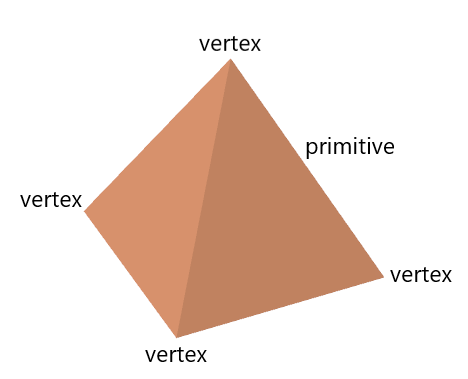
- Vertex specification is the setting up of the data of the vertices for the primitives that are to be rendered.
- A vertex is a point in space that is generally defined with x, y and z co-ordinates.
- A primitive is a simple shape defined using one or more vertices.
- This process is carried out within the application itself.
- It uses the Vertex Array Objects (VAOs) and Vertex Buffer Objects (VBOs).
A Vertex Array Object defines what data a vertex has, such as position, texture, colour, etc. whereas a Vertex Buffer Object defines the data itself.
6.2 Vertex Shader
- Vertex shaders take each individual vertex and then processes them separately.
- They receive the attribute inputs from the vertex rendering and then convert each input vertex to a single ouput vertex based on a user-defined program (shader).
- Additional outputs can also be specified that can be picked up and utilized by some other user-defined shaders in the pipeline somewhere down the line.
- Here is an example of the Vertex Shader.
#version 330

layout (location=0) in vec3 pos;

void main()
{
    gl_position = vec4(pos, 1.0);
}
6.3 Tessellation
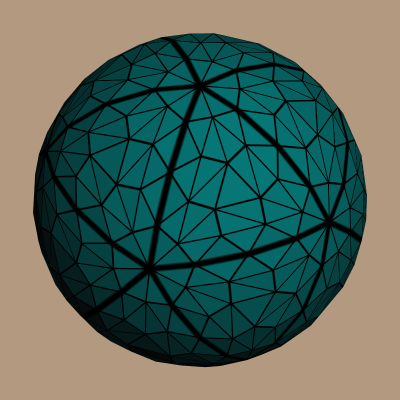
- Tessellation allows one to divide the data up into smaller primitives.
- It can be used to add much higher levels of details in a dynamic manner.
- Many games such as Rise of the Tomb Raider, Crysis 2, etc. use tessellation to add extreme level of details dynamically.
6.4 Geometry Shader
- Just like a vertex shader handles vertices separately, the Geometry Shader is similarly used to handle primitives (groups of vertices) by themselves.
- It takes the primitives as input and the outputs their vertices to render and create the given primitive. It is also capable of outputting more than one primitive.
- It can also alter or modify the data of the given primitive and even their types (lines, triangles, etc.) to produce new primitives.
6.5 Vertex Post-Processing
Once the vertices have been processed based on the user-driven shaders, they further undergo a number of fixed-function processing steps.
Transform Feedback: If enabled, it can be used to store the outputs and results of the vertex and geometry shaders onto buffer objects that are specifically setup for this purpose. This allows the user to use the data that has been saved to the buffer at a later stage.
Clipping: With clipping, one can ensure that the primitives that won't be visible to the user are removed to prevent unnecessary usage of resources.
Face culling: In any of the games that you might have played, when you look at certain objects, they always look as if they have complete depth and have been rendered completely, from top to bottom and back to front.
Face culling allows one to avoid rendering primitives that are facing away from the user or viewer. They might be in the frame, but not exactly in front of the user's perspective. For example, if you are looking at a car from the front, you won't be able to see what's behind it, so what is the point in rendering that part unnecessarily? This can save resources as well.
6.6 Primitive Assembly
- Vertex data from prior stages are composed into a sequence of primitives. This process is known as Primitive Assembly.
- For example, if triangles are being rendered, then 9 vertices would be outputted as 3 triangles, with each triangle have 3 vertices.
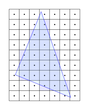
6.7 Rasterization
- In this stage, the primitives are converted into fragments.
- Fragments are pieces of data for each pixel that are obtained from the rasterization process. They can be used to compute the final data for a pixel in the output framebuffer.
- Fragment data is interpolated based on its position relative to each vertex.
6.8 Fragment Shader
- As the name suggests, the Fragment Shader handles and processes data for each fragment separately.
- Covers some important aspects such as the color of the pixel that the fragment covers and more.
- Here is an example of the Fragment Shader.
#version 330

out vec4 colour;

void main()
{
    colour = vec4(0.3, 0.5, 0.7, 1.0);
}
6.9 Per-Sample Operations
- In the Per-Sample Operations stage, fragments are individually run through a set of operations or tests to check if they should be drawn onto the screen or not.
- It also has a depth test, which determines if something is in front of the point that is being drawn.
- It also has Color Blending, through which (by making use of defined operations) fragment colors are blended together with any overlapping fragments. It is most commonly used to handle transparent objects.
7. Advantages of OpenGL
- Industry Standard: OpenGL specification is guided by an independent consortium, the OpenGL Architecture Review Board, due to which it has broad industry support.
- Stability: All the features provided by OpenGL are well controlled. Backward compatibility also ensures that the existing applications and features don't become obsolete at any point.
- Reliability and Portability: All OpenGL applications produce consistent visual display results on any OpenGL API-compliant hardware, regardless of the operating system or windowing system.
- Huge Community: OpenGL also has a huge community behind it and that also has its own benefits.
- Documentation: OpenGL is very properly documented and all of its features, from individual functions to shaders, are readily available and can be easily obtained.
With this article at OpenGenus, you must have the complete introduction to OpenGL.