Open-Source Internship opportunity by OpenGenus for programmers. Apply now.
In this article, we have explored Code Generation in Compiler Design in depth including challenges and key techniques like Instruction Selection, Register Allocation using Graph Coloring, Instruction Ordering and much more.
Table of Contents
- Introduction
- Role of Code Generator
- Challenges of Generation
- Instruction Selection
- Macro Expansion
- Graph Covering
- Register Allocation
- Graph Colouring
- Instruction Ordering
- Example Generation
- Overview
Pre-requisite: Graph Coloring
Introduction
In this article we will cover the basis of code generation within the compiler, how it works and its function. We will explain various functions that the code generator can perform and an example of generation.
Role of Code Generator
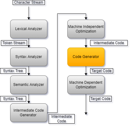
The code generator within a compiler is responsible for converting intermediate code to target code. It is part of the final stages of compilation, within the overall hierarchy of a compiler it is located between the optimisation steps.

To convert the optimised intermediate code into target code, the code generator generally carries out 3 tasks.
- Instruction Selection
- Register Allocation
- Instruction Ordering
Additionally, the code converter should:
- Preserve original function of the program defined by programmer
- Generate efficient target code in both time and space
Challenges of Generation
Code generation is a tricky problem due to the high complexity of operations required and because code itself is extremely volatile since every intermediate code that the complier deals with will be different.
Each aspect of code generation involves a complicated process, for example, optimal register assignment is NP-Complete. This is done by a graphing algorithm which we will discuss later in the article. To solve this, heuristics can be used in order to approximate the solution. Additionally, individual architectural features will also become an issue to deal with, such as registers which are reserved for special instructions (eg. float calculations), the results that are stored in the accumulator and the specific combination of registers used for double-precision arithmetic.
Much like register allocation, optimal instruction ordering is also NP-complete. To complete this, graph covering algorithms are used, for complex programs, it is NP-Complete since to represent these programs in a graphical format, DAGs are used. To solve this greedy algorithms are used to get a reasonable solution.
Instruction selection is also a complex process since correct and optimal instructions have to be chosen based on a multitude of factors, such as the level of the intermediate code, the individual instruction set available to the processor architecture or the desired output code.
In the remainder of the article, we will dive into the processes that the code generator carries out to perform these actions and we will see how algorithms can help with the optimal generation.
Instruction Selection
The complexity of the instructions that the compiler uses is based on three factors:
- The level of intermediate code
- Generally speaking, the lower level the intermediate code is, the more efficient. For example, "intsize" vs "2"
- The nature of the instruction set
- Whether the set is uniform and complete will affect the target code. For example, floats need to be stored in unique registers
- The desired attributes of the target code
- Context and data processing will affect the target code. For example, incrementing a variable could be "INC a" vs "LDR R1, a; ADD R1, R1, #1; STR a, R1"
Macro Expansion
The most basic approach to choosing the most optimal instructions is macro expansion. In this method, templates are matched over the intermediate code and when a match is found, a macro is executed, with the matched intermediate code as an input. This will then output the correct instructions appropriate for the intermediate code inputted. The downside to this is that macro expansion is only usually efficient for simple code therefore we can combine this with peephole optimisation in order to replace simple instructions with equivalent more complex ones which may increase performance and reduce the size of the code.
Graph Covering
A second method for selecting the instructions is through graph covering. This method will transform the intermediate representation into a graphical format and then cover the graph with patterns. Each pattern has a "cost" which is the number of cycles it takes to execute said instructions, the goal of this method therefore is to minimise the cost of the selected patterns across the graph. For tree graphs, it can be found in linear time through the use of dynamic programming however, it becomes nondeterministic-polynomial complete once the graph becomes full-fledged or a DAG therefore needs to be solved with greedy algorithms or similar.
Register Allocation
Register allocation is choosing the optimal variables within a program to store into registers. The job of the allocator is to decide which variables to store in registers, and then which are the most efficient registers for those variables. To do this, although different strategies may be employed, it relies on a core set of actions:
- Move insertion - Increasing the number of move instructions for variables between registers, meaning variables will be passed around registers instead of being stationary. This is used in cases such as a split live range approach in graph colouring, which will be explained later in the article.
- Spilling - Choosing to store a variable in memory rather than a register.
- Assignment - Assigning variable to a register.
- Coalescing - Limiting the movement between registers which in turn will limit instruction count. This can be seen as the opposite of move insertion as its aim is to keep a variable within one register its whole lifespan.
Graph Colouring
Efficient register allocation can be classed as Nondeterministic-Polynomial Complete. We can use graph colouring allocation to solve this. In this approach, the nodes of a graph are the variables we want to allocate to registers. The edges connect the variables which interfere for example, two variables which live at the same program point. This can be then solved as a graph colouring problem, ensuring that all nodes which are connected by edges do not receive the same colour.
Example program:
a = c + d
e = a + b
f = e - 1
We know that the variable "a" can be reused after the "e = a + b" assignment since it is not used again in the last line and therefore is not live. This can also be applied to e and f, meaning that a, e and f can all be allocated to the one register (R1).
R1 = R2 + R3
R1 = R1 + R4
R1 = R1 - 1
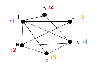
Using the principles of graph colouring discussed above we can assign colours to each node where each node is a register, from this we can then ensure that all variables that are live at the same time do not receive allocation to the same register.

Let's say we have k number of machine registers available, if we use the same number of colours in the graph as registers, we can say that it is k-colourable. In this case, we have 4 registers and 4 colours therefore our graph is k-colourable. This means that we have obtained a register allocation that uses no more than k registers, or in other words, as many as we need.
From our colour graph, we can turn the above into:

This is the conversion to machine code of our example program using the graph colouring approach to register allocation, we can see that this is an optimised allocation in which no registers interfere with each other.
Instruction Ordering
Generally, high level languages have a thread of execution which it follows in order to execute statements in a defined order. The order of execution does however affect performance for example the more consistent that the compiler can make the execution, the better so load instructions should be placed after other load instructions in order to maintain cache coherency, store instructions therefore should be placed after other store instructions and so on.
R0 = A
R1 = B
R2 = C
R3 = R0 + R1
R4 = R2 + R3
d = R4

or

R0 = A
R1 = B
R2 = R0 + R1
R0 = C
R3 = R2 + R0
d = R3
Arguably, the second version is more efficient due to it needing less registers to execute however, the second version was only possible due to the order of operations allowing it to use less. Here we can see that the order of operations will affect performance, which is why it is needed during code generation.
Example Generation
Input code:
I = J + K

Intermediate code is then generated:
R1 = J
R2 = K
R1 = R1 + R2
I = R1

Then, the target code:
LDR R1, J //loads value of j into r1
LDR R2, K //loads value of k into r2
ADD R1, R1, R2 //adds r1 and r2, stores it into r1
STR I, R1 //stores the value of R1 to I
Here we can see an example of how the compiler goes about generating code for our target machine. First, the high-level code is inputted in which the intermediate representation is output. Then, through the methods and optimisation techniques discussed earlier, the instructions are generated for the target, leaving us with the appropriate machine code for this program.
Overview
In this article at OpenGenus, we have covered the principles of code generation by the compiler. We have gone over its roles in generation and numerous methods in which it can achieve this. Additionally, we have described techniques the compiler uses to optimise its process and then finally, gave an example of how high-level language would be converted into machine code.
