
In this article, we have explored 3D U-Net model which is an enhancement of 2D U-Net model and is used for Volumetric Segmentation applications.
Table of contents:
- Introduction
- 3D U-Net Architecture
- Some Details About Implematation
- Application Scenarios For Volumetric Segmentation With 3D U-Net
- Semi-Automatic Segmentation
- Fully-automated Segmentation
- A Comparison Between 2D and 3D U-Net
- Conclusion
Pre-requisites:
Introduction
3D U-Net was introduced shortly after U-Net to process volumetric data which is abundant in medical data analysis. It is based on the previous architecture which consists of an encoder part to analyze the whole image and a decoder part to produce full resolution segmentation. 3D U-Net takes 3D volume as inputs and applies 3D convolution, 3D maxpooling and 3D up-convolutional layers unlike 2D Unet which has an entirely 2D architecture.
3D U-Net Architecture
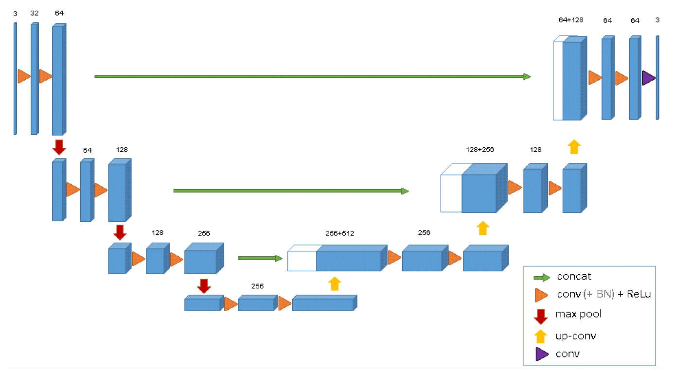
3D U-Net has an analysis path(left) and a synthesis path(right). In the analysis path, there are two 3 x 3 x 3 convolutions in each layer.
Each of these layers is followed by a ReLU and then a 2 × 2 × 2 max-pooling with strides of two in each dimension. In the sysnthesis path, each layer consists of an upconvolution of 2 × 2 × 2 by strides of two in each dimension. It is followed by two 3 × 3 × 3 convolutions each followed by a ReLu. Essential high-resolution features to the synthesis path are provided by shortcut connections from layers of equal resolution in the analysis path. A 1 × 1 × 1 convolution in the last layer reduces the number of output channels to the number of labels which is 3. The architecture has a total of 19069955 parameters.
To avoid bottlenecks, the number of channels are doubled before max-pooling. Though only three layers are shown in the diagram but more layers are used during implementation.
Each block uses batch normalization beore each ReLU. During training, each batch is normalized with its mean and standard deviation. Using these values global statistics are updated. This is followed by a layer for learning scale and bias explicitly. During testing, these global statistics and learned scale and bias are used for normalization.
Some Details About Implematation
- Only three samples of Xenopus kidney embryos are used for the implementation.
- Different labels were given to different structures like 0: "inside the tubule"; 1: "tubule"; 2: "background", and 3: "unlabeled".
- Voxels with label 3 have a weight 0.
- Experiments are run on on down-sampled versions of the original resolution by factor of two in each dimension.
- So, the data sizes used in the experiments are
248 × 244 × 64,245 × 244 × 56and246 × 244 × 59inx × y × zdimensions for the sample 1, 2, and 3, respectively.
Application Scenarios For Volumetric Segmentation With 3D U-Net
Semi-Automatic Segmentation
For semi-automatic segmentation, it is assumed that a full segmnetaion of some volumetric images is needed and does not have prior segmentations. The set of all 77 manually annotated slices from all 3 sampled are partitioned into a 3-fold cross validation both with and without batch normalization. We remove the test slices and keep them unlabeled.
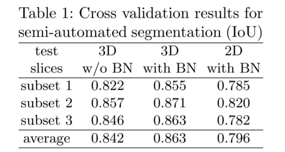
Intersection Over Union(IoU) is an accuracy metric to compare ground truth to predictd 3D volume. More the numner of slices, more is the IoU.
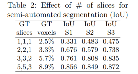
The effect of the number of annotated slices to the network performance was also measured. 1 annotated slice in each orthogonal direction was used in the start and the number was increased gradually. For each sample(S1, S2, S3), the high performance gain with every additional ground truth(GT) slices is reported.
Fully-automated Segmentation
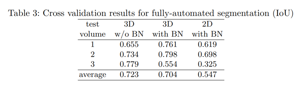
Here it is assumed that a large number of images recorded in a comparable setting are to be segmented. The training is done on two (partially annotated) kidney volumes and this network is then used to segment the third volume. Batch normalization improves the result but in the third setting the outcome is not poroductive. The large difference in the datasets might be responsible for this effect.
A Comparison Between 2D and 3D U-Net
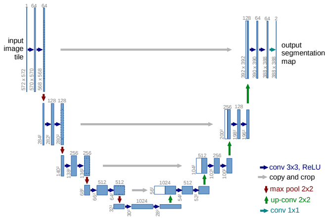
2D U-Net is an extension of Fully Connected Network. It was first designed for biomedical image segmentation. 2D U-Net is a symmetric architecture and is divided into an endcoder-decoder path/contracting-expanding path. The 2D and 3D U-net architecture is quite similar. In 2D U-Net the encoder path consists of repeated application of two 3x3 convolutions and each convolution is followed by a ReLU and batch normalization. The convolution operation here is called a down convolution. After that a 2x2 max pooling operation is done. In the contracting path, the feature maps get spatially smaller. The expanding path takes our small feature maps through a series of up-sampling and up-convolution steps to get back to the original size of the image.
In 3D U-Net, all 2D opearations are replaced by their 3D counterparts. The 2D convolutions become 3D convolutions, and the 2D pooling layers become 3D pooling layers. 3D U-Net allows us to pass 3D subvolumes and get output for every voxel in the volume.
Conclusion
This article at OpenGenus gives an overview of the 3D U-Net architecture and also shows a comparison with its 2D counterpart.
Reference